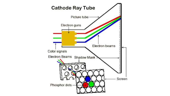
The initial concept for this project was an idea for a mechanical/artistic replication of a CRT television set. CRT sets used a controlled beam to excite phosphorescent dots and raster an image across a screen.
To recreate this mechanically our plan was to utilize a single RGB LED and move that single point source across an area, 3D or 2D while using long exposure photography/videography to produce an output image.
We ran into several issues in the hardware and electronics side to execute this output, but we were able to develop several interesting results. With more time to purchase the correct electronics we would have been able to accomplish this original plan

4 degree of freedom robot arm
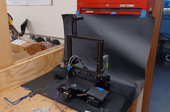
Ender 3 used for motion platform
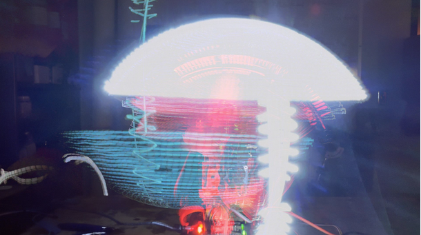
When starting this project we attempted to use the robotic arm provided to us, but quickly realized that one of the biggest obstacles would be the limitation of the robotic arm. The robotic arm created unstable images when we gave it an image to draw. The unstable movement can be seen in the wobbly horizontal lines in the below image
A large portion of this project was conducted in Grasshopper, a visual scripting plugin for Rhino. This was chosen over a traditional programming language as it is quicker to iterate/rework a script and is built to handle geometry particularly well.
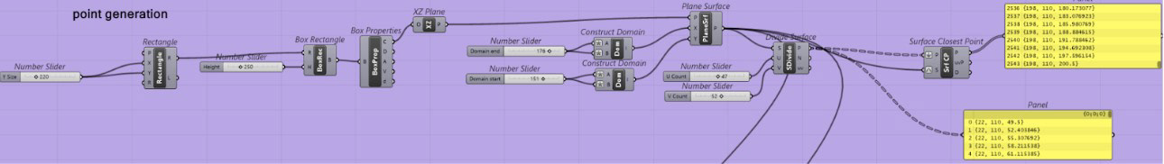
The general process in grasshopper was to first define the workspace of our motion platform (the ender 3) then a plane to contain our painting or our digital “canvas” was defined. From here it will be possible to map our designated point in an area that fits within the capabilities of the robot
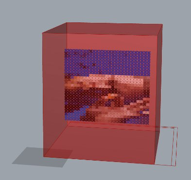
To sample an image in grasshopper we define a list of points and a bounding area. We select the “resolution” from our generated point list and then feed those points into the image sampler. This outputs a list of RGB or brightness values with indices that correspond to our point list.
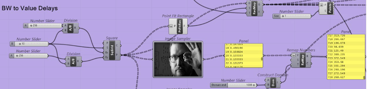
Since we ruled out RGB painting due to a lack of an integrated control system, we output the brightness values of an image. We had assumed that the long exposure app averaged out the brightness overtime with a bias towards some threshold/the bright sides. From this I made the script to extend the delay from movement based on a pixels brightness.
This was that output. We determined the issue was that most long exposure processes will only output the brightest pixels across the whole exposure time. Since we didn’t have integrated pixel control with the gcode movement, it caused any moves to basically wash out or scramble the image we were trying to paint. The final version of the GCODE was designed to only use black and white images to help mitigate this issue.
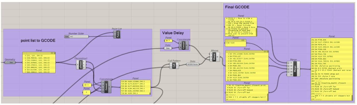
This section translates the points and delays into GCODE formatted specifically to run on Marlin, the firmware for the ender 3 system.
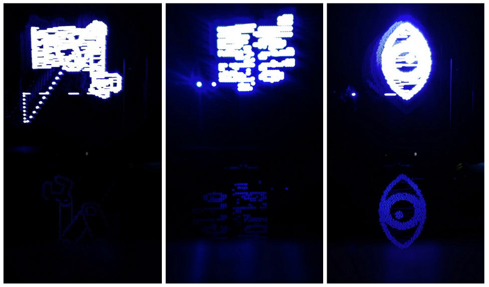
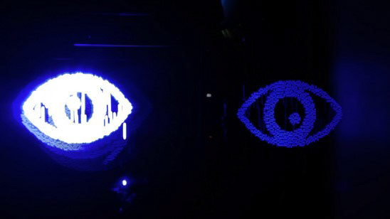
Resulting Images: Robot arm, "Hello World", and an eye
It was discovered that the reflection in the images provided a better result than the actual light captured. It can be inferred from these images that the brightness of the LED was too high. However, the reflection that it created at the bottom of the images was sufficient in showing the prescribed images.
If we were to continue on this project, we would definitely like to integrate LED control to the motion system and the ability to change colors. This could be done with a SKR E3 Board for the Ender 3 with built-in Neopixel port. This could also be done with a more accurate motion system with Arduino Control. Additionally, this project could benefit from having path/vector drawing associated with it. This would be adding bezier curves, waypoints, or trajectory generation to the motion of the system.